Your cart is currently empty!
Category: ims Db
-
Khóa học miễn phí IMS DB – Home nhận dự án làm có lương
IMS DB Tutorial
IMS stands for Information Management System. IMS was developed by IBM with Rockwell and Caterpillar in year 1966 for the Apollo program to send a man to the moon. It started the database management system revolution and still continues to evolve to meet data processing requirements. IMS provides an easy-to-use, reliable, and standard environment for executing high-performance transactions. IMS database is used by high-level programming languages like COBOL to store data in hierarchical arrangement and access it.
Audience
This tutorial is designed for software programmers who are interested in understanding the concepts of IMS database starting from scratch. This tutorial gives enough understanding on IMS data management from where you can take yourself to higher levels of expertise.
Prerequisites
Before proceeding with this tutorial, you should have a basic understanding COBOL programming skills. A basic knowledge of database concepts will help you understand the IMS database management system.
Khóa học lập trình tại Toidayhoc vừa học vừa làm dự án vừa nhận lương: Khóa học lập trình nhận lương tại trung tâm Toidayhoc
Khóa học miễn phí IMS DB – Quick Guide nhận dự án làm có lương
IMS DB – Quick Guide
IMS DB – Overview
A Brief Overview
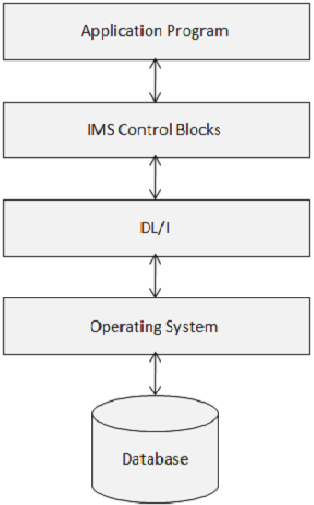
Database is a collection of correlated data items. These data items are organized and stored in a manner to provide fast and easy access. IMS database is a hierarchical database where data is stored at different levels and each entity is dependent on higher level entities. The physical elements on an application system that use IMS are shown in the following figure.
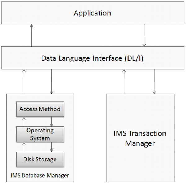
Database Management
A Database Management system is a set of application programs used for storing, accessing, and managing data in the database. IMS database management system maintains integrity and allows fast recovery of data by organizing it in such a way that it is easy to retrieve. IMS maintains a large amount of world”s corporate data with the help of its database management system.
Transaction Manager
The function of transaction manager is to provide a communication platform between the database and the application programs. IMS acts as a transaction manager. A transaction manager deals with the end-user to store and retrieve data from the database. IMS can use IMS DB or DB2 as its back-end database to store the data.
DL/I – Data Language Interface
DL/I comprises of application programs that grant access to the data stored in the database. IMS DB uses DL/I which serves as the interface language that programmers use for accessing the database in an application program. We will discuss this in more detail in the upcoming chapters.
Characteristics of IMS
Points to note −
- IMS supports applications from different languages such as Java and XML.
- IMS applications and data can be accessed over any platform.
- IMS DB processing is very fast as compared to DB2.
Limitations of IMS
Points to note −
- Implementation of IMS DB is very complex.
- IMS predefined tree structure reduces flexibility.
- IMS DB is difficult to manage.
IMS DB – Structure
Hierarchical Structure
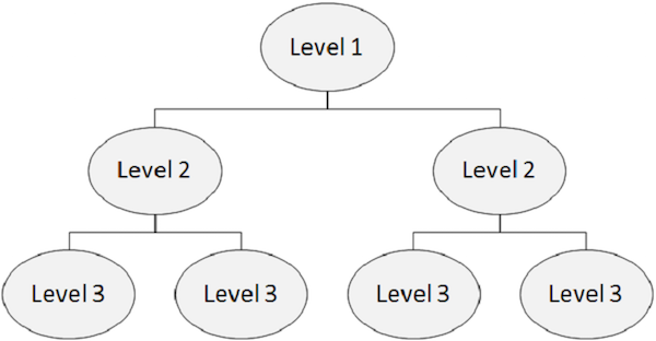
An IMS database is a collection of data accommodating physical files. In a hierarchical database, the topmost level contains the general information about the entity. As we proceed from the top level to the bottom levels in the hierarchy, we get more and more information about the entity.
Each level in the hierarchy contains segments. In standard files, it is difficult to implement hierarchies but DL/I supports hierarchies. The following figure depicts the structure of IMS DB.
Segment
Points to note −
-
A segment is created by grouping of similar data together.
-
It is the smallest unit of information that DL/I transfers to and from an application program during any input-output operation.
-
A segment can have one or more data fields grouped together.
In the following example, the segment Student has four data fields.
| Student | |||
|---|---|---|---|
| Roll Number | Name | Course | Mobile NUmber |
Field
Points to note−
-
A field is a single piece of data in a segment. For example, Roll Number, Name, Course, and Mobile Number are single fields in the Student segment.
-
A segment consists of related fields to collect the information of an entity.
-
Fields can be used as a key for ordering the segments.
-
Fields can be used as a qualifier for searching information about a particular segment.
Segment Type
Points to note −
-
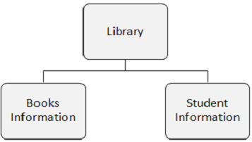
Segment Type is a category of data in a segment.
-
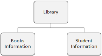
A DL/I database can have 255 different segment types and 15 levels of hierarchy.
-
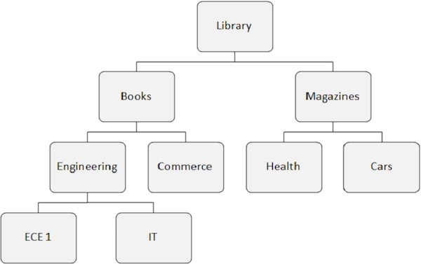
In the following figure, there are three segments namely, Library, Books Information, and Student Information.
Segment Occurrence
Points to note −
-
A segment occurrence is an individual segment of a particular type containing user data. In the above example, Books Information is one segment type and there can any number of occurrences of it, as it can store the information about any number of books.
-
Within the IMS Database, there is only one occurrence of each segment type, but there can be an unlimited number of occurrences of each segment type.
IMS DB – DL/I Terminology
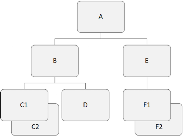
Hierarchical databases work on the relationships between two or more segments. The following example shows how segments are related to each other in the IMS database structure.
Root Segment
Points to note −
-
The segment that lies at the top of the hierarchy is called the root segment.
-
The root segment is the only segment through which all dependent segments are accessed.
-
The root segment is the only segment in the database which is never a child segment.
-
There can be only one root segment in the IMS database structure.
-
For example, ”A” is the root segment in the above example.
Parent Segment
Points to note −
-
A parent segment has one or more dependent segments directly below it.
-
For example, ”A”, ”B”, and ”E” are the parent segments in the above example.
Dependent Segment
Points to note −
-
All segments other than the root segment are known as dependent segments.
-
Dependent segments depend on one or more segments to present complete meaning.
-
For example, ”B”, ”C1”, ”C2”, ”D”, ”E”, ”F1” and ”F2” are dependent segments in our example.
Child Segment
Points to note −
-
Any segment having a segment directly above it in the hierarchy is known as a child segment.
-
Each dependent segment in the structure is a child segment.
-
For example, ”B”, ”C1”, ”C2”, ”D”, ”E”, ”F1” and ”F2” are child segments.
Twin Segments
Points to note −
-
Two or more segment occurrences of a particular segment type under a single parent segment are called twin segments.
-
For example, ”C1” and ”C2” are twin segments, so do ”F1” and ”F2” are.
Sibling Segment
Points to note −
-
Sibling segments are the segments of different types and the same parent.
-
For example, ”B” and ”E” are sibling segments. Similarly, ”C1”, ”C2”, and ”D” are sibling segments.
Database Record
Points to note −
-
Each occurrence of the root segment, plus all the subordinate segment occurrences make one database record.
-
Every database record has only one root segment but it may have any number of segment occurrences.
-
In standard file processing, a record is a unit of data that an application program uses for certain operations. In DL/I, that unit of data is known as a segment. A single database record has many segment occurrences.
Database Path
Points to note −
-
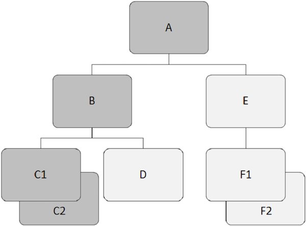
A path is the series of segments that starts from the root segment of a database record to any specific segment occurrence.
-
A path in the hierarchy structure need not be complete to the lowest level. It depends on how much information we require about an entity.
-
A path must be continuous and we cannot skip intermediate levels in the structure.
-
In the following figure, the child records in dark grey color show a path which starts from ”A” and goes through ”C2”.
IMS DB – DL/I Processing
IMS DB stores data at different levels. Data is retrieved and inserted by issuing DL/I calls from an application program. We will discuss about DL/I calls in detail in the upcoming chapters. Data can be processed in the following two ways −
- Sequential Processing
- Random Processing
Sequential Processing
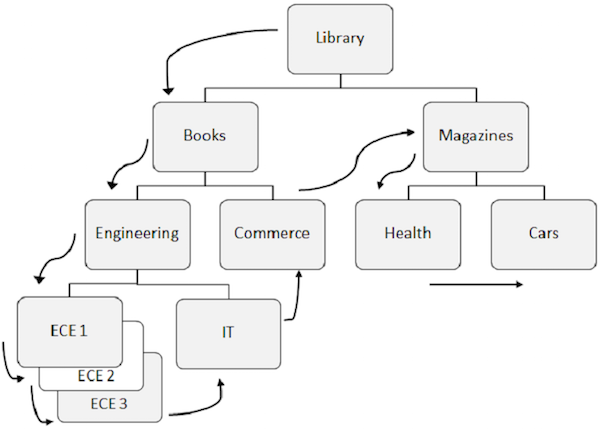
When segments are retrieved sequentially from the database, DL/I follows a predefined pattern. Let us understand the sequential processing of IMS DB.
Listed below are the points to note about sequential processing −
-
Predefined pattern for accessing data in DL/I is first down the hierarchy, then left to right.
-
The root segment is retrieved first, then DL/I moves to the first left child and it goes down till the lowest level. At the lowest level, it retrieves all the occurrences of twin segments. Then it goes to the right segment.
-
To understand better, observe the arrows in the above figure that show the flow for accessing the segments. Library is the root segment and the flow starts from there and goes till cars to access a single record. The same process is repeated for all occurrences to get all the data records.
-
While accessing data, the program uses the position in the database which helps to retrieve and insert segments.
Random Processing
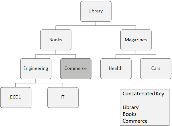
Random processing is also known as direct processing of data in IMS DB. Let us take an example to understand random processing in IMS DB −
Listed below are the points to note about random processing −
-
Segment occurrence that needs to be retrieved randomly requires key fields of all the segments it depends upon. These key fields are supplied by the application program.
-
A concatenated key completely identifies the path from the root segment to the segment which you want to retrieve.
-
Suppose you want to retrieve an occurrence of the Commerce segment, then you need to supply the concatenated key field values of the segments it depends upon, such as Library, Books, and Commerce.
-
Random processing is faster than sequential processing. In real-world scenario, the applications combine both sequential and random processing methods together to achieve best results.
Key Field
Points to note −
-
A key field is also known as a sequence field.
-
A key field is present within a segment and it is used to retrieve the segment occurrence.
-
A key field manages the segment occurrence in ascending order.
-
In each segment, only a single field can be used as a key field or sequence field.
Search Field
As mentioned, only a single field can be used as a key field. If you want to search for the contents of other segment fields which are not key fields, then the field which is used to retrieve the data is known as a search field.
IMS DB – Control Blocks
IMS Control Blocks define the structure of the IMS database and a program”s access to them. The following diagram shows the structure of IMS control blocks.
DL/I uses the following three types of Control Blocks −
- Database Descriptor (DBD)
- Program Specification Block (PSB)
- Access Control Block (ACB)
Database Descriptor (DBD)
Points to note −
-
DBD describes the complete physical structure of the database once all the segments have been defined.
-
While installing a DL/I database, one DBD must be created as it is required to access the IMS database.
-
Applications can use different views of the DBD. They are called Application Data Structures and they are specified in the Program Specification Block.
-
The Database Administrator creates a DBD by coding DBDGEN control statements.
DBDGEN
DBDGEN is a Database Descriptor Generator. Creating control blocks is the responsibility of the Database Administrator. All the load modules are stored in the IMS library. Assembly Language macro statements are used to create control blocks. Given below is a sample code that shows how to create a DBD using DBDGEN control statements −
PRINT	NOGEN
DBD	NAME=LIBRARY,ACCESS=HIDAM
DATASET	DD1=LIB,DEVICE=3380
SEGM	NAME=LIBSEG,PARENT=0,BYTES=10
FIELD	NAME=(LIBRARY,SEQ,U),BYTES=10,START=1,TYPE=C
SEGM	NAME=BOOKSEG,PARENT=LIBSEG,BYTES=5
FIELD	NAME=(BOOKS,SEQ,U),BYTES=10,START=1,TYPE=C
SEGM	NAME=MAGSEG,PARENT=LIBSEG,BYTES=9
FIELD	NAME=(MAGZINES,SEQ),BYTES=8,START=1,TYPE=C
DBDGEN
FINISH
END
Let us understand the terms used in the above DBDGEN −
-
When you execute the above control statements in JCL, it creates a physical structure where LIBRARY is the root segment, and BOOKS and MAGZINES are its child segments.
-
The first DBD macro statement identifies the database. Here, we need to mention the NAME and ACCESS which is used by DL/I to access this database.
-
The second DATASET macro statement identifies the file that contains the database.
-
The segment types are defined using the SEGM macro statement. We need to specify the PARENT of that segment. If it is a Root segment, then mention PARENT=0.
The following table shows parameters used in FIELD macro statement −
| S.No | Parameter & Description |
|---|---|
| 1 |
Name Name of the field, typically 1 to 8 characters long |
| 2 |
Bytes Length of the field |
| 3 |
Start Position of field within segment |
| 4 |
Type Data type of the field |
| 5 |
Type C Character data type |
| 6 |
Type P Packed decimal data type |
| 7 |
Type Z Zoned decimal data type |
| 8 |
Type X Hexadecimal data type |
| 9 |
Type H Half word binary data type |
| 10 |
Type F Full word binary data type |
Program Specification Block (PSB)
The fundamentals of PSB are as given below −
-
A database has a single physical structure defined by a DBD but the application programs that process it can have different views of the database. These views are called application data structure and are defined in the PSB.
-
No program can use more than one PSB in a single execution.
-
Application programs have their own PSB and it is common for application programs that have similar database processing requirements to share a PSB.
-
PSB consists of one or more control blocks called Program Communication Blocks (PCBs). The PSB contains one PCB for each DL/I database the application program will access. We will discuss more about PCBs in the upcoming modules.
-
PSBGEN must be performed to create a PSB for the program.
PSBGEN
PSBGEN is known as Program Specification Block Generator. The following example creates a PSB using PSBGEN −
PRINT   NOGEN
PCB     TYPE=DB,DBDNAME=LIBRARY,KEYLEN=10,PROCOPT=LS
SENSEG  NAME=LIBSEG
SENSEG  NAME=BOOKSEG,PARENT=LIBSEG
SENSEG  NAME=MAGSEG,PARENT=LIBSEG
PSBGEN  PSBNAME=LIBPSB,LANG=COBOL
END
Let us understand the terms used in the above DBDGEN −
-
The first macro statement is the Program Communication Block (PCB) that describes the database Type, Name, Key-Length, and Processing Option.
-
DBDNAME parameter on the PCB macro specifies the name of the DBD. KEYLEN specifies the length of the longest concatenated key. The program can process in the database. PROCOPT parameter specifies the program”s processing options. For example, LS means only LOAD Operations.
-
SENSEG is known as Segment Level Sensitivity. It defines the program”s access to parts of the database and it is identified at the segment level. The program has access to all the fields within the segments to which it is sensitive. A program can also have field-level sensitivity. In this, we define a segment name and the parent name of the segment.
-
The last macro statement is PCBGEN. PSBGEN is the last statement telling there are no more statements to process. PSBNAME defines the name given to the output PSB module. The LANG parameter specifies the language in which the application program is written, e.g., COBOL.
Access Control Block (ACB)
Listed below are the points to note about access control blocks −
-
Access Control Blocks for an application program combines the Database Descriptor and the Program Specification Block into an executable form.
-
ACBGEN is known as Access Control Blocks Generator. It is used to generate ACBs.
-
For online programs, we need to pre-build ACBs. Hence the ACBGEN utility is executed before executing the application program.
-
For batch programs, ACBs can be generated at execution time too.
IMS DB – Programming
An application program which includes DL/I calls cannot execute directly. Instead, a JCL is required to trigger the IMS DL/I batch module. The batch initialization module in IMS is DFSRRC00. The application program and the DL/I module execute together. The following diagram shows the structure of an application program which includes DL/I calls to access a database.
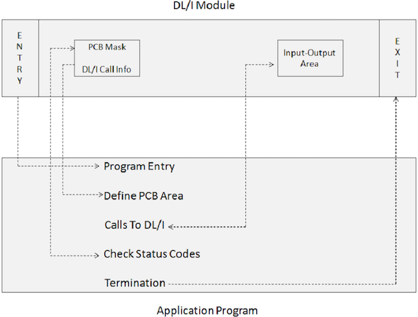
The application program interfaces with IMS DL/I modules via the following program elements −
-
An ENTRY statement specifies that the PCBs are utilized by the program.
-
A PCB-mask co-relates with the information preserved in the pre-constructed PCB which receives return information from the IMS.
-
An Input-Output Area is used for passing data segments to and from the IMS database.
-
Calls to DL/I specify the processing functions such as fetch, insert, delete, replace, etc.
-
Check Status Codes is used to check the SQL return code of the processing option specified to inform whether the operation was successful or not.
-
A Terminate statement is used to end the processing of the application program which includes the DL/I.
Segments Layout
As of now, we learnt that the IMS consists of segments which are used in high-level programming languages to access data. Consider the following IMS database structure of a Library which we have seen earlier and here we see the layout of its segments in COBOL −
01 LIBRARY-SEGMENT.
   05 BOOK-ID        PIC X(5).
   05 ISSUE-DATE     PIC X(10).
   05 RETURN-DATE    PIC X(10).
   05 STUDENT-ID     PIC A(25).

01 BOOK-SEGMENT.
   05 BOOK-ID        PIC X(5).
   05 BOOK-NAME      PIC A(30).
   05 AUTHOR         PIC A(25).

01 STUDENT-SEGMENT.
   05 STUDENT-ID     PIC X(5).
   05 STUDENT-NAME   PIC A(25).
   05 DIVISION       PIC X(10).
Application Program Overview
The structure of an IMS application program is different from that of a Non-IMS application program. An IMS program cannot be executed directly; rather it is always called as a subroutine. An IMS application program consists of Program Specification Blocks to provide a view of the IMS database.
The application program and the PSBs linked to that program are loaded when we execute an application program which includes IMS DL/I modules. Then the CALL requests triggered by the application programs are executed by the IMS module.
IMS Services
The following IMS services are used by the application program −
- Accessing database records
- Issuing IMS commands
- Issuing IMS service calls
- Checkpoint calls
- Sync calls
- Sending or receiving messages from online user terminals
IMS DB – Cobol Basics
We include DL/I calls inside COBOL application program to communicate with IMS database. We use the following DL/I statements in COBOL program to access the database −
- Entry Statement
- Goback Statement
- Call Statement
Entry Statement
It is used to pass the control from the DL/I to the COBOL program. Here is the syntax of the entry statement −
ENTRY ''DLITCBL'' USING pcb-name1
                     [pcb-name2]
The above statement is coded in the Procedure Division of a COBOL program. Let us go into the details of the entry statement in COBOL program −
-
The batch initialization module triggers the application program and is executed under its control.
-
The DL/I loads the required control blocks and modules and the application program, and control is given to the application program.
-
DLITCBL stands for DL/I to COBOL. The entry statement is used to define the entry point in the program.
-
When we call a sub-program in COBOL, its address is also provided. Likewise, when the DL/I gives the control to the application program, it also provides the address of each PCB defined in the program”s PSB.
-
All the PCBs used in the application program must be defined inside the Linkage Section of the COBOL program because PCB resides outside the application program.
-
The PCB definition inside the Linkage Section is called as PCB Mask.
-
The relation between PCB masks and actual PCBs in storage is created by listing the PCBs in the entry statement. The sequence of listing in the entry statement should be same as they appear in the PSBGEN.
Goback Statement
It is used to pass the control back to the IMS control program. Following is the syntax of the Goback statement −
GOBACK
Listed below are the fundamental points to note about the Goback statement −
-
GOBACK is coded at the end of the application program. It returns the control to DL/I from the program.
-
We should not use STOP RUN as it returns the control to the operating system. If we use STOP RUN, the DL/I never gets a chance to perform its terminating functions. That is why, in DL/I application programs, Goback statement is used.
-
Before issuing a Goback statement, all the non-DL/I datasets used in the COBOL application program must be closed, otherwise the program will terminate abnormally.
Call Statement
Call statement is used to request for DL/I services such as executing certain operations on the IMS database. Here is the syntax of the call statement −
CALL ''CBLTDLI'' USING DLI Function Code
                        PCB Mask
                        Segment I/O Area
                        [Segment Search Arguments]
The syntax above shows parameters which you can use with the call statement. We will discuss each of them in the following table −
| S.No. | Parameter & Description |
|---|---|
| 1 |
DLI Function Code Identifies the DL/I function to be performed. This argument is the name of the four character fields that describe the I/O operation. |
| 2 |
PCB Mask The PCB definition inside the Linkage Section is called as PCB Mask. They are used in the entry statement. No SELECT, ASSIGN, OPEN, or CLOSE statements are required. |
| 3 |
Segment I/O Area Name of an input/output work area. This is an area of the application program into which the DL/I puts a requested segment. |
| 4 |
Segment Search Arguments These are optional parameters depending on the type of the call issued. They are used to search data segments inside the IMS database. |
Given below are the points to note about the Call statement −
-
CBLTDLI stands for COBOL to DL/I. It is the name of an interface module that is link edited with your program’s object module.
-
After each DL/I call, the DLI stores a status code in the PCB. The program can use this code to determine whether the call succeeded or failed.
Example
For more understanding of COBOL, you can go through our COBOL tutorial . The following example shows the structure of a COBOL program that uses IMS database and DL/I calls. We will discuss in detail each of the parameters used in the example in the upcoming chapters.
IDENTIFICATION DIVISION.
PROGRAM-ID. TEST1.
DATA DIVISION.
WORKING-STORAGE SECTION.
01 DLI-FUNCTIONS.
   05 DLI-GU        PIC X(4)    VALUE ''GU  ''.
   05 DLI-GHU       PIC X(4)    VALUE ''GHU ''.
   05 DLI-GN        PIC X(4)    VALUE ''GN  ''.
   05 DLI-GHN       PIC X(4)    VALUE ''GHN ''.
   05 DLI-GNP       PIC X(4)    VALUE ''GNP ''.
   05 DLI-GHNP      PIC X(4)    VALUE ''GHNP''.
   05 DLI-ISRT      PIC X(4)    VALUE ''ISRT''.
   05 DLI-DLET      PIC X(4)    VALUE ''DLET''.
   05 DLI-REPL      PIC X(4)    VALUE ''REPL''.
   05 DLI-CHKP      PIC X(4)    VALUE ''CHKP''.
   05 DLI-XRST      PIC X(4)    VALUE ''XRST''.
   05 DLI-PCB       PIC X(4)    VALUE ''PCB ''.
01  SEGMENT-I-O-AREA        PIC X(150).
LINKAGE SECTION.
01  STUDENT-PCB-MASK.
   05 STD-DBD-NAME              PIC X(8).
   05 STD-SEGMENT-LEVEL         PIC XX.
   05 STD-STATUS-CODE           PIC XX.
   05 STD-PROC-OPTIONS          PIC X(4).
   05 FILLER                    PIC S9(5) COMP.
   05 STD-SEGMENT-NAME          PIC X(8).
   05 STD-KEY-LENGTH            PIC S9(5) COMP.
   05 STD-NUMB-SENS-SEGS        PIC S9(5) COMP.
   05 STD-KEY                   PIC X(11).
PROCEDURE DIVISION.
ENTRY ''DLITCBL'' USING STUDENT-PCB-MASK.
A000-READ-PARA.
110-GET-INVENTORY-SEGMENT.
   CALL ‘CBLTDLI’ USING DLI-GN
                  STUDENT-PCB-MASK
                  SEGMENT-I-O-AREA.
GOBACK.
IMS DB – DL/I Functions
DL/I function is the first parameter that is used in a DL/I call. This function tells which operation is going to be performed on the IMS database by the IMS DL/I call. The syntax of DL/I function is as follows −
01 DLI-FUNCTIONS.
   05 DLI-GU        PIC X(4)    VALUE ''GU  ''.
   05 DLI-GHU       PIC X(4)    VALUE ''GHU ''.
   05 DLI-GN        PIC X(4)    VALUE ''GN  ''.
   05 DLI-GHN       PIC X(4)    VALUE ''GHN ''.
   05 DLI-GNP       PIC X(4)    VALUE ''GNP ''.
   05 DLI-GHNP      PIC X(4)    VALUE ''GHNP''.
   05 DLI-ISRT      PIC X(4)    VALUE ''ISRT''.
   05 DLI-DLET      PIC X(4)    VALUE ''DLET''.
   05 DLI-REPL      PIC X(4)    VALUE ''REPL''.
   05 DLI-CHKP      PIC X(4)    VALUE ''CHKP''.
   05 DLI-XRST      PIC X(4)    VALUE ''XRST''.
   05 DLI-PCB       PIC X(4)    VALUE ''PCB ''.
This syntax represents the following key points −
-
For this parameter, we can provide any four-character name as a storage field to store the function code.
-
DL/I function parameter is coded in the working storage section of the COBOL program.
-
For specifying the DL/I function, the programmer needs to code one of the 05 level data names such as DLI-GU in a DL/I call, since COBOL does not allow to code literals on a CALL statement.
-
DL/I functions are divided into three categories: Get, Update, and Other functions. Let us discuss each of them in detail.
Get Functions
Get functions are similar to the read operation supported by any programming language. Get function is used to fetch segments from an IMS DL/I database. The following Get functions are used in IMS DB −
- Get Unique
- Get Next
- Get Next within Parent
- Get Hold Unique
- Get Hold Next
- Get Hold Next within Parent
Let us consider the following IMS database structure to understand the DL/I function calls −
Get Unique
”GU” code is used for the Get Unique function. It works similar to the random read statement in COBOL. It is used to fetch a particular segment occurrence based on the field values. The field values can be provided using segment search arguments. The syntax of a GU call is as follows −
CALL ''CBLTDLI'' USING DLI-GU
                     PCB Mask
                     Segment I/O Area
                     [Segment Search Arguments]
If you execute the above call statement by providing appropriate values for all parameters in the COBOL program, you can retrieve the segment in the segment I/O area from the database. In the above example, if you provide the field values of Library, Magazines, and Health, then you get the desired occurrence of the Health segment.
Get Next
”GN” code is used for the Get Next function. It works similar to the read next statement in COBOL. It is used to fetch segment occurrences in a sequence. The predefined pattern for accessing data segment occurrences is down the hierarchy, then left to right. The syntax of a GN call is as follows −
CALL ''CBLTDLI'' USING DLI-GN
                     PCB Mask
                     Segment I/O Area
                     [Segment Search Arguments]
If you execute the above call statement by providing appropriate values for all parameters in the COBOL program, you can retrieve the segment occurrence in the segment I/O area from the database in a sequential order. In the above example, it starts with accessing the Library segment, then Books segment, and so on. We perform the GN call again and again, until we reach the segment occurrence we want.
Get Next within Parent
”GNP” code is used for Get Next within Parent. This function is used to retrieve segment occurrences in sequence subordinate to an established parent segment. The syntax of a GNP call is as follows −
CALL ''CBLTDLI'' USING DLI-GNP
                     PCB Mask
                     Segment I/O Area
                     [Segment Search Arguments]
Get Hold Unique
”GHU” code is used for Get Hold Unique. Hold function specifies that we are going to update the segment after retrieval. The Get Hold Unique function corresponds to the Get Unique call. Given below is the syntax of a GHU call −
CALL ''CBLTDLI'' USING DLI-GHU
                     PCB Mask
                     Segment I/O Area
                     [Segment Search Arguments]
Get Hold Next
”GHN” code is used for Get Hold Next. Hold function specifies that we are going to update the segment after retrieval. The Get Hold Next function corresponds to the Get Next call. Given below is the syntax of a GHN call −
CALL ''CBLTDLI'' USING DLI-GHN
                     PCB Mask
                     Segment I/O Area
                     [Segment Search Arguments]
Get Hold Next within Parent
”GHNP” code is used for Get Hold Next within Parent. Hold function specifies that we are going to update the segment after retrieval. The Get Hold Next within Parent function corresponds to the Get Next within Parent call. Given below is the syntax of a GHNP call −
CALL ''CBLTDLI'' USING DLI-GHNP
                     PCB Mask
                     Segment I/O Area
                     [Segment Search Arguments]
Update Functions
Update functions are similar to re-write or insert operations in any other programming language. Update functions are used to update segments in an IMS DL/I database. Before using the update function, there must be a successful call with Hold clause for the segment occurrence. The following Update functions are used in IMS DB −
- Insert
- Delete
- Replace
Insert
”ISRT” code is used for the Insert function. The ISRT function is used to add a new segment to the database. It is used to change an existing database or load a new database. Given below is the syntax of an ISRT call −
CALL ''CBLTDLI'' USING DLI-ISRT
                     PCB Mask
                     Segment I/O Area
                     [Segment Search Arguments]
Delete
”DLET” code is used for the Delete function. It is used to remove a segment from an IMS DL/I database. Given below is the syntax of a DLET call −
CALL ''CBLTDLI'' USING DLI-DLET
                     PCB Mask
                     Segment I/O Area
                     [Segment Search Arguments]
Replace
”REPL” code is used for Get Hold Next within Parent. The Replace function is used to replace a segment in the IMS DL/I database. Given below is the syntax of an REPL call −
CALL ''CBLTDLI'' USING DLI-REPL
                     PCB Mask
                     Segment I/O Area
                     [Segment Search Arguments]
Other Functions
The following other functions are used in IMS DL/I calls −
- Checkpoint
- Restart
- PCB
Checkpoint
”CHKP” code is used for the Checkpoint function. It is used in the recovery features of IMS. Given below is the syntax of a CHKP call −
CALL ''CBLTDLI'' USING DLI-CHKP
                     PCB Mask
                     Segment I/O Area
                     [Segment Search Arguments]
Restart
”XRST” code is used for the Restart function. It is used in the restart features of IMS. Given below is the syntax of an XRST call −
CALL ''CBLTDLI'' USING DLI-XRST
                     PCB Mask
                     Segment I/O Area
                     [Segment Search Arguments]
PCB
PCB function is used in CICS programs in the IMS DL/I database. Given below is the syntax of a PCB call −
CALL ''CBLTDLI'' USING DLI-PCB
                     PCB Mask
                     Segment I/O Area
                     [Segment Search Arguments]
You can find more details about these functions in the recovery chapter.
IMS DB – PCB Mask
PCB stands for Program Communication Block. PCB Mask is the second parameter used in the DL/I call. It is declared in the linkage section. Given below is the syntax of a PCB Mask −
01 PCB-NAME.
   05 DBD-NAME         PIC X(8).
   05 SEG-LEVEL        PIC XX.
   05 STATUS-CODE      PIC XX.
   05 PROC-OPTIONS     PIC X(4).
   05 RESERVED-DLI     PIC S9(5).
   05 SEG-NAME         PIC X(8).
   05 LENGTH-FB-KEY    PIC S9(5).
   05 NUMB-SENS-SEGS   PIC S9(5).
   05 KEY-FB-AREA      PIC X(n).
Here are the key points to note −
-
For each database, the DL/I maintains an area of storage that is known as the program communication block. It stores the information about the database that are accessed inside the application programs.
-
The ENTRY statement creates a connection between the PCB masks in the Linkage Section and the PCBs within the program’s PSB. The PCB masks used in a DL/I call tells which database to use for operation.
-
You can assume this is similar to specifying a file name in a COBOL READ statement or a record name in a COBOL write statement. No SELECT, ASSIGN, OPEN, or CLOSE statements are required.
-
After each DL/I call, the DL/I stores a status code in the PCB and the program can use that code to determine whether the call succeeded or failed.
PCB Name
Points to note −
-
PCB Name is the name of the area which refers to the entire structure of the PCB fields.
-
PCB Name is used in program statements.
-
PCB Name is not a field in the PCB.
DBD Name
Points to note −
-
DBD name contains the character data. It is eight bytes long.
-
The first field in the PCB is the name of the database being processed and it provides the DBD name from the library of database descriptions associated with a particular database.
Segment Level
Points to note −
-
Segment level is known as Segment Hierarchy Level Indicator. It contains character data and is two bytes long.
-
A segment level field stores the level of the segment that was processed. When a segment is retrieved successfully, the level number of the retrieved segment is stored here.
-
A segment level field never has a value greater than 15 because that is the maximum number of levels permitted in a DL/I database.
Status Code
Points to note −
-
Status code field contains two bytes of character data.
-
Status code contains the DL/I status code.
-
Spaces are moved to the status code field when DL/I completes the processing of calls successfully.
-
Non-space values indicate that the call was not successful.
-
Status code GB indicates end-of-file and status code GE indicates that the requested segment is not found.
Proc Options
Points to note −
-
Proc options are known as processing options which contain four-character data fields.
-
A Processing Option field indicates what kind of processing the program is authorized to do on the database.
Reserved DL/I
Points to note −
-
Reserved DL/I is known as the reserved area of the IMS. It stores four bytes binary data.
-
IMS uses this area for its own internal linkage related to an application program.
Segment Name
Points to note −
-
SEG Name is known as segment name feedback area. It contains 8 bytes of character data.
-
The name of the segment is stored in this field after each DL/I call.
Length FB Key
Points to note −
-
Length FB key is known as the length of the key feedback area. It stores four bytes of binary data.
-
This field is used to report the length of the concatenated key of the lowest level segment processed during the previous call.
-
It is used with the key feedback area.
Number of Sensitivity Segments
Points to note −
-
Number of sensitivity segments store four bytes binary data.
-
It defines to which level an application program is sensitive. It represents a count of number of segments in the logical data structure.
Key Feedback Area
Points to note −
-
Key feedback area varies in length from one PCB to another.
-
It contains the longest possible concatenated key that can be used with the program’s view of the database.
-
After a database operation, DL/I returns the concatenated key of the lowest level segment processed in this field, and it returns the length of the key in the key length feedback area.
IMS DB – SSA
SSA stands for Segment Search Arguments. SSA is used to identify the segment occurrence being accessed. It is an optional parameter. We can include any number of SSAs depending on the requirement. There are two types of SSAs −
- Unqualified SSA
- Qualified SSA
Unqualified SSA
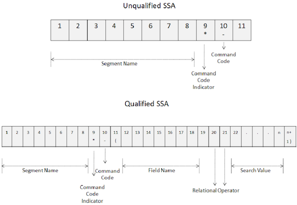
An unqualified SSA provides the name of the segment being used inside the call. Given below is the syntax of an unqualified SSA −
01 UNQUALIFIED-SSA.
   05  SEGMENT-NAME  PIC X(8).
   05  FILLER        PIC X     VALUE SPACE.
The key points of unqualified SSA are as follows −
-
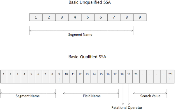
A basic unqualified SSA is 9 bytes long.
-
The first 8 bytes hold the segment name which is being used for processing.
-
The last byte always contains space.
-
DL/I uses the last byte to determine the type of SSA.
-
To access a particular segment, move the name of the segment in the SEGMENT-NAME field.
The following images show the structures of unqualified and qualified SSAs −
Qualified SSA
A Qualified SSA provides the segment type with the specific database occurrence of a segment. Given below is the syntax of a Qualified SSA −
01 QUALIFIED-SSA.
   05  SEGMENT-NAME  PIC X(8).
   05  FILLER        PIC X(01)      VALUE ''(''.
   05  FIELD-NAME    PIC X(8).
   05  REL-OPR       PIC X(2).
   05  SEARCH-VALUE  PIC X(n).
   05  FILLER        PIC X(n+1) VALUE '')''.
The key points of qualified SSA are as follows −
-
The first 8 bytes of a qualified SSA holds the segment name being used for processing.
-
The ninth byte is a left parenthesis ”(”.
-
The next 8 bytes starting from the tenth position specifies the field name which we want to search.
-
After the field name, in the 18th and 19th positions, we specify two-character relational operator code.
-
Then we specify the field value and in the last byte, there is a right parenthesis ”)”.
The following table shows the relational operators used in a Qualified SSA.
| Relational Operator | Symbol | Description |
|---|---|---|
| EQ | = | Equal |
| NE | ~= ˜ | Not equal |
| GT | > | Greater than |
| GE | >= | Greater than or equal |
| LT | << | Less than |
| LE | <= | Less than or equal |
Command Codes
Command codes are used to enhance the functionality of DL/I calls. Command codes reduce the number of DL/I calls, making the programs simple. Also, it improves the performance as the number of calls is reduced. The following image shows how command codes are used in unqualified and qualified SSAs −
The key points of command codes are as follows −
-
To use command codes, specify an asterisk in the 9th position of the SSA as shown in the above image.
-
Command code is coded at the tenth position.
-
From 10th position onwards, DL/I considers all characters to be command codes until it encounters a space for an unqualified SSA and a left parenthesis for a qualified SSA.
The following table shows the list of command codes used in SSA −
| Command Code | Description |
|---|---|
| C | Concatenated Key |
| D | Path Call |
| F | First Occurrence |
| L | Last Occurrence |
| N | Path Call Ignore |
| P | Set Parentage |
| Q | Enqueue Segment |
| U | Maintain Position at this level |
| V | Maintain Position at this and all above levels |
| – | Null Command Code |
Multiple Qualifications
The fundamental points of multiple qualifications are as follows −
-
Multiple qualifications are required when we need to use two or more qualifications or fields for comparison.
-
We use Boolean operators like AND and OR to connect two or more qualifications.
-
Multiple qualifications can be used when we want to process a segment based on a range of possible values for a single field.
Given below is the syntax of Multiple Qualifications −
01 QUALIFIED-SSA.
   05  SEGMENT-NAME  PIC X(8).
   05  FILLER        PIC X(01)      VALUE ''(''.
   05  FIELD-NAME1   PIC X(8).
   05  REL-OPR       PIC X(2).
   05  SEARCH-VALUE1 PIC X(m).
   05  MUL-QUAL      PIC X      VALUE ''&''.
   05  FIELD-NAME2   PIC X(8).
   05  REL-OPR       PIC X(2).
   05  SEARCH-VALUE2 PIC X(n).
   05  FILLER        PIC X(n+1) VALUE '')''.
MUL-QUAL is a short term for MULtiple QUALIification in which we can provide boolean operators like AND or OR.
IMS DB – Data Retrieval
The various data retrieval methods used in IMS DL/I calls are as follows −
- GU Call
- GN Call
- Using Command Codes
- Multiple Processing
Let us consider the following IMS database structure to understand the data retrieval function calls −
GU Call
The fundamentals of GU call are as follows −
-
GU call is known as Get Unique call. It is used for random processing.
-
If an application does not update the database regularly or if the number of database updates is less, then we use random processing.
-
GU call is used to place the pointer at a particular position for further sequential retrieval.
-
GU calls are independent of the pointer position established by the previous calls.
-
GU call processing is based on the unique key fields supplied in the call statement.
-
If we supply a key field that is not unique, then DL/I returns the first segment occurrence of the key field.
CALL ''CBLTDLI'' USING DLI-GU
                     PCB-NAME
                     IO-AREA
                     LIBRARY-SSA
                     BOOKS-SSA
                     ENGINEERING-SSA
                     IT-SSA
The above example shows we issue a GU call by providing a complete set of qualified SSAs. It includes all the key fields starting from the root level to the segment occurrence that we want to retrieve.
GU Call Considerations
If we do not provide the complete set of qualified SSAs in the call, then DL/I works in the following way −
-
When we use an unqualified SSA in a GU call, DL/I accesses the first segment occurrence in the database that meets the criteria you specify.
-
When we issue a GU call without any SSAs, DL/I returns the first occurrence of the root segment in the database.
-
If some SSAs at intermediate levels are not mentioned in the call, then DL/I uses either the established position or the default value of an unqualified SSA for the segment.
Status Codes
The following table shows the relevant status codes after a GU call −
| S.No | Status Code & Description |
|---|---|
| 1 |
Spaces Successful call |
| 2 |
GE DL/I could not find a segment that met the criteria specified in the call |
GN Call
The fundamentals of GN call are as follows −
-
GN call is known as Get Next call. It is used for basic sequential processing.
-
The initial position of the pointer in the database is before the root segment of the first database record.
-
The database pointer position is before the next segment occurrence in the sequence, after a successful GN call.
-
The GN call starts through the database from the position established by the previous call.
-
If a GN call is unqualified, it returns the next segment occurrence in the database regardless of its type, in hierarchical sequence.
-
If a GN call includes SSAs, then DL/I retrieves only segments that meet the requirements of all specified SSAs.
CALL ''CBLTDLI'' USING DLI-GN
                     PCB-NAME
                     IO-AREA
                     BOOKS-SSA
The above example shows we issue a GN call providing the starting position to read the records sequentially. It fetches the first occurrence of the BOOKS segment.
Status Codes
The following table shows the relevant status codes after a GN call −
| S.No | Status Code & Description |
|---|---|
| 1 |
Spaces Successful call |
| 2 |
GE DL/I could not find a segment that met the criteria specified in the call. |
| 3 |
GA An unqualified GN call moves up one level in the database hierarchy to fetch the segment. |
| 4 |
GB End of database is reached and segment not found. |
|
GK An unqualified GN call tries to fetch a segment of a particular type other than the one just retrieved but stays in the same hierarchical level. |
Command Codes
Command codes are used with calls to fetch a segment occurrence. The various command codes used with calls are discussed below.
F Command Code
Points to note −
-
When an F command code is specified in a call, the call processes the first occurrence of the segment.
-
F command codes can be used when we want to process sequentially and it can be used with GN calls and GNP calls.
-
If we specify an F command code with a GU call, it does not have any significance, as GU calls fetch the first segment occurrence by default.
L Command Code
Points to note −
-
When an L command code is specified in a call, the call processes the last occurrence of the segment.
-
L command codes can be used when we want to process sequentially and it can be used with GN calls and GNP calls.
D Command Code
Points to note −
-
D command code is used to fetch more than one segment occurrences using just a single call.
-
Normally DL/I operates on the lowest level segment specified in an SSA, but in many cases, we want data from other levels as well. In those cases, we can use the D command code.
-
D command code makes easy retrieval of the entire path of segments.
C Command Code
Points to note −
-
C command code is used to concatenate keys.
-
Using relational operators is a bit complex, as we need to specify a field name, a relational operator, and a search value. Instead, we can use a C command code to provide a concatenated key.
The following example shows the use of C command code −
01 LOCATION-SSA.
   05 FILLER		     PIC X(11) VALUE ‘INLOCSEG*C(‘.
   05 LIBRARY-SSA      PIC X(5).
   05 BOOKS-SSA        PIC X(4).
   05 ENGINEERING-SSA  PIC X(6).
   05 IT-SSA           PIC X(3)
   05 FILLER		     PIC X	VALUE ‘)’.

CALL ''CBLTDLI'' USING DLI-GU
                     PCB-NAME
                     IO-AREA
                     LOCATION-SSA
P Command Code
Points to note −
-
When we issue a GU or GN call, the DL/I establishes its parentage at the lowest level segment that is retrieved.
-
If we include a P command code, then the DL/I establishes its parentage at a higher level segment in the hierarchical path.
U Command Code
Points to note −
-
When a U command code is specified in an unqualified SSA in a GN call, the DL/I restricts the search for the segment.
-
U command code is ignored if it is used with a qualified SSA.
V Command Code
Points to note −
-
V command code works similar to the U command code, but it restricts the search of a segment at a particular level and all levels above the hierarchy.
-
V command code is ignored when used with a qualified SSA.
Q Command Code
Points to note −
-
Q command code is used to enqueue or reserve a segment for exclusive use of your application program.
-
Q command code is used in an interactive environment where another program might make a change to a segment.
Multiple Processing
A program can have multiple positions in the IMS database which is known as multiple processing. Multiple processing can be done in two ways −
- Multiple PCBs
- Multiple Positioning
Multiple PCBs
Multiple PCBs can be defined for a single database. If there are multiple PCBs, then an application program can have different views of it. This method for implementing multiple processing is inefficient because of the overheads imposed by the extra PCBs.
Multiple Positioning
A program can maintain multiple positions in a database using a single PCB. This is achieved by maintaining a distinct position for each hierarchical path. Multiple positioning is used to access segments of two or more types sequentially at the same time.
IMS DB – Data Manipulation
The different data manipulation methods used in IMS DL/I calls are as follows −
- ISRT Call
- Get Hold Calls
- REPL Call
- DLET Call
Let us consider the following IMS database structure to understand the data manipulation function calls −
ISRT Call
Points to note −
-
ISRT call is known as Insert call which is used to add segment occurrences to a database.
-
ISRT calls are used for loading a new database.
-
We issue an ISRT call when a segment description field is loaded with data.
-
An unqualified or qualified SSA must be specified in the call so that the DL/I knows where to place a segment occurrence.
-
We can use a combination of both unqualified and qualified SSA in the call. A qualified SSA can be specified for all the above levels. Let us consider the following example −
CALL ''CBLTDLI'' USING DLI-ISRT
                     PCB-NAME
                     IO-AREA
                     LIBRARY-SSA
                     BOOKS-SSA
                     UNQUALIFIED-ENGINEERING-SSA
The above example shows we are issuing an ISRT call by providing a combination of qualified and unqualified SSAs.
When a new segment that we are inserting has a unique key field, then it is added at the proper position. If the key field is not unique, then it is added by the rules defined by a database administrator.
When we issue an ISRT call without specifying a key field, then the insert rule tells where to place the segments relative to existing twin segments. Given below are the insert rules −
-
First − If the rule is first, the new segment is added before any existing twins.
-
Last − If the rule is last, the new segment is added after all existing twins.
-
Here − If the rule is here, it is added at the current position relative to existing twins, which may be first, last, or anywhere.
Status Codes
The following table shows the relevant status codes after an ISRT call −
| S.No | Status Code & Description |
|---|---|
| 1 |
Spaces Successful call |
| 2 |
GE Multiple SSAs are used and the DL/I cannot satisfy the call with the specified path. |
| 3 |
II Try to add a segment occurrence that is already present in the database. |
| 4 |
LB / LC LD / LE We get these status codes while load processing. In most cases, they indicate that you are not inserting the segments in an exact hierarchical sequence. |
Get Hold Call
Points to note −
-
There are three types of Get Hold call which we specify in a DL/I call:
-
Get Hold Unique (GHU)
-
Get Hold Next (GHN)
-
Get Hold Next within Parent (GHNP)
-
-
Hold function specifies that we are going to update the segment after retrieval. So before an REPL or DLET call, a successful hold call must be issued telling the DL/I an intent to update the database.
REPL Call
Points to note −
-
After a successful get hold call, we issue an REPL call to update a segment occurrence.
-
We cannot change the length of a segment using an REPL call.
-
We cannot change the value of a key field using an REPL call.
-
We cannot use a qualified SSA with an REPL call. If we specify a qualified SSA, then the call fails.
CALL ''CBLTDLI'' USING DLI-GHU
                     PCB-NAME
                     IO-AREA
                     LIBRARY-SSA
                     BOOKS-SSA
                     ENGINEERING-SSA
                     IT-SSA.

*Move the values which you want to update in IT segment occurrence*

CALL ‘CBLTDLI’ USING DLI-REPL
                     PCB-NAME
                     IO-AREA.
The above example updates the IT segment occurrence using an REPL call. First, we issue a GHU call to get the segment occurrence we want to update. Then, we issue an REPL call to update the values of that segment.
DLET Call
Points to note −
-
DLET call works much in the same way as an REPL call does.
-
After a successful get hold call, we issue a DLET call to delete a segment occurrence.
-
We cannot use a qualified SSA with a DLET call. If we specify a qualified SSA, then the call fails.
CALL ''CBLTDLI'' USING DLI-GHU
                     PCB-NAME
                     IO-AREA
                     LIBRARY-SSA
                     BOOKS-SSA
                     ENGINEERING-SSA
                     IT-SSA.

CALL ‘CBLTDLI’ USING DLI-DLET
                     PCB-NAME
                     IO-AREA.
The above example deletes the IT segment occurrence using a DLET call. First, we issue a GHU call to get the segment occurrence we want to delete. Then, we issue a DLET call to update the values of that segment.
Status Codes
The following table shows the relevant status codes after an REPL or a DLET call −
| S.No | Status Code & Description |
|---|---|
| 1 |
Spaces Successful call |
| 2 |
AJ Qualified SSA used on REPL or DLET call. |
| 3 |
DJ Program issues a replace call without an immediately preceding get hold call. |
| 4 |
DA Program makes a change to the segment’s key field before issuing the REPL or DLET call |
IMS DB – Secondary Indexing
Secondary Indexing is used when we want to access a database without using the complete concatenated key or when we do not want to use the sequence primary fields.
Index Pointer Segment
DL/I stores the pointer to segments of the indexed database in a separate database. Index pointer segment is the only type of secondary index. It consists of two parts −
- Prefix Element
- Data Element
Prefix Element
The prefix part of the index pointer segment contains a pointer to the Index Target Segment. Index target segment is the segment that is accessible using the secondary index.
Data Element
The data element contains the key value from the segment in the indexed database over which the index is built. This is also known as the index source segment.
Here are the key points to note about Secondary Indexing −
-
The index source segment and the target source segment need not be the same.
-
When we set up a secondary index, it is automatically maintained by the DL/I.
-
The DBA defines many secondary indexes as per the multiple access paths. These secondary indexes are stored in a separate index database.
-
We should not create more secondary indexes, as they impose additional processing overhead on the DL/I.
Secondary Keys
Points to note −
-
The field in the index source segment over which the secondary index is built is called as the secondary key.
-
Any field can be used as a secondary key. It need not be the segments sequence field.
-
Secondary keys can be any combination of single fields within the index source segment.
-
Secondary key values do not have to be unique.
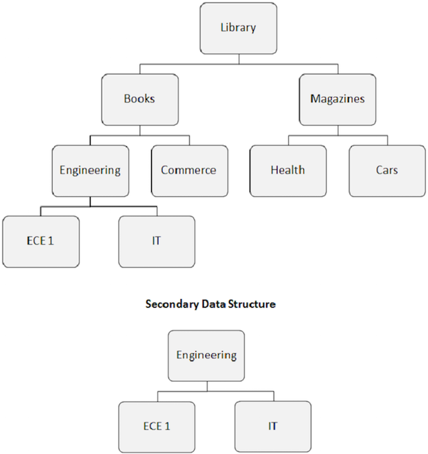
Secondary Data Structures
Points to note −
-
When we build a secondary index, the apparent hierarchical structure of the database is also changed.
-
The index target segment becomes the apparent root segment. As shown in the following image, the Engineering segment becomes the root segment, even if it is not a root segment.
-
The rearrangement of the database structure caused by the secondary index is known as the secondary data structure.
-
Secondary data structures do not make any changes to the main physical database structure present on the disk. It is just a way to alter the database structure in front of the application program.
Independent AND Operator
Points to note −
-
When an AND (* or &) operator is used with secondary indexes, it is known as a dependent AND operator.
-
An independent AND (#) allows us to specify qualifications that would be impossible with a dependent AND.
-
This operator can be used only for secondary indexes where the index source segment is dependent on the index target segment.
-
We can code an SSA with an independent AND to specify that an occurrence of the target segment be processed based on the fields in two or more dependent source segments.
01 ITEM-SELECTION-SSA.
   05 FILLER           PIC X(8).
   05 FILLER           PIC X(1) VALUE ''(''.
   05 FILLER           PIC X(10).
   05 SSA-KEY-1        PIC X(8).
   05 FILLER           PIC X   VALUE ''#''.
   05 FILLER           PIC X(10).
   05 SSA-KEY-2        PIC X(8).
   05 FILLER           PIC X   VALUE '')''.
Sparse Sequencing
Points to note −
-
Sparse sequencing is also known as Sparse Indexing. We can remove some of the index source segments from the index using sparse sequencing with secondary index database.
-
Sparse sequencing is used to improve the performance. When some occurrences of the index source segment are not used, we can remove that.
-
DL/I uses a suppression value or a suppression routine or both to determine whether a segment should be indexed.
-
If the value of a sequence field in the index source segment matches a suppression value, then no index relationship is established.
-
The suppression routine is a user-written program that evaluates the segment and determines whether or not it should be indexed.
-
When sparse indexing is used, its functions are handled by the DL/I. We do not need to make special provisions for it in the application program.
DBDGEN Requirements
As discussed in earlier modules, DBDGEN is used to create a DBD. When we create secondary indexes, two databases are involved. A DBA needs to create two DBDs using two DBDGENs for creating a relationship between an indexed database and a secondary indexed database.
PSBGEN Requirements
After creating the secondary index for a database, the DBA needs to create the PSBs. PSBGEN for the program specifies the proper processing sequence for the database on the PROCSEQ parameter of the PSB macro. For the PROCSEQ parameter, the DBA codes the DBD name for the secondary index database.
IMS DB – Logical Database
IMS database has a rule that each segment type can have only one parent. This limits the complexity of the physical database. Many DL/I applications require a complex structure that allows a segment to have two parent segment types. To overcome this limitation, DL/I allows the DBA to implement logical relationships in which a segment can have both physical and logical parents. We can create additional relationships within one physical database. The new data structure after implementing the logical relationship is known as the Logical Database.
Logical Relationship
A logical relationship has the following properties −
-
A logical relationship is a path between two segments which are related logically and not physically.
-
Usually a logical relationship is established between separate databases. But it is possible to have a relationship between the segments of one particular database.
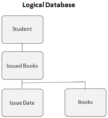
The following image shows two different databases. One is a Student database, and the other is a Library database. We create a logical relationship between the Books Issued segment from the Student database and the Books segment from the Library database.
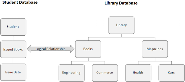
This is how the logical database looks when you create a logical relationship −
Logical Child Segment
Logical child segment is the basis of a logical relationship. It is a physical data segment but for DL/I, it appears as if it has two parents. The Books segment in the above example has two parent segments. Issued books segment is the logical parent and Library segment is the physical parent. One logical child segment occurrence has only one logical parent segment occurrence and one logical parent segment occurrence can have many logical child segment occurrences.
Logical Twins
Logical twins are the occurrences of a logical child segment type that are all subordinate to a single occurrence of the logical parent segment type. DL/I makes the logical child segment appear similar to an actual physical child segment. This is also known as a virtual logical child segment.
Types of Logical Relationships
A DBA creates logical relationships between segments. To implement a logical relationship, the DBA has to specify it in the DBDGENs for the involved physical databases. There are three types of logical relationships −
- Unidirectional
- Bidirectional Virtual
- Bidirectional Physical
Unidirectional
The logical connection goes from the logical child to the logical parent and it cannot go the other way around.
Bidirectional Virtual
It allows access in both the directions. The logical child in its physical structure and the corresponding virtual logical child can be seen as paired segments.
Bidirectional Physical
The logical child is a physically stored subordinate to both its physical and logical parents. To application programs, it appears the same way as a bidirectional virtual logical child.
Programming Considerations
The programming considerations for using a logical database are as follows −
-
DL/I calls to access the database remains same with the logical database too.
-
Program specification block indicates the structure which we use in our calls. In some cases, we cannot identify that we are using a logical database.
-
Logical relationships add a new dimension to database programming.
-
You must be careful while working with logical databases, as two databases are integrated together. If you modify one database, the same modifications must be reflected in the other database.
-
Program specifications should indicate what processing is allowed on a database. If a processing rule is violated, you get a non-blank status code.
Concatenated Segment
A logical child segment always begins with the complete concatenated key of the destination parent. This is known as the Destination Parent Concatenated Key (DPCK). You need to always code the DPCK at the start of your segment I/O area for a logical child. In a logical database, the concatenated segment makes the connection between segments that are defined in different physical databases. A concatenated segment consists of the following two parts −
- Logical child segment
- Destination parent segment
A logical child segment consists of the following two parts −
- Destination Parent Concatenated Key (DPCK)
- Logical child user data
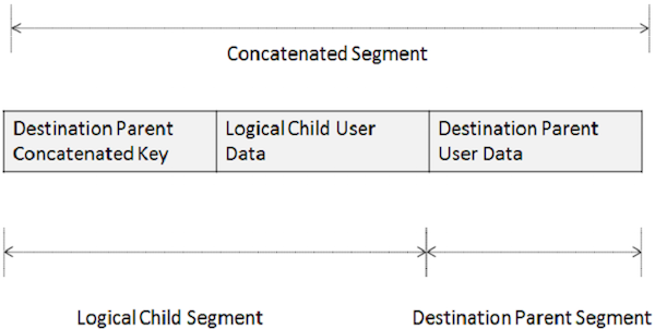
When we work with concatenated segments during update, it may be possible to add or change the data in both the logical child and the destination parent with a single call. This also depends on the rules the DBA specified for the database. For an insert, provide the DPCK in the right position. For a replace or delete, do not change the DPCK or the sequence field data in either part of the concatenated segment.
IMS DB – Recovery
The database administrator needs to plan for the database recovery in case of system failures. Failures can be of many types such as application crashes, hardware errors, power failures, etc.
Simple Approach
Some simple approaches to database recovery are as follows −
-
Make periodical backup copies of important datasets so that all transactions posted against the datasets are retained.
-
If a dataset is damaged due to a system failure, that problem is corrected by restoring the backup copy. Then the accumulated transactions are re-posted to the backup copy to bring them up-to-date.
Disadvantages of Simple Approach
The disadvantages of simple approach to database recovery are as follows −
-
Re-posting the accumulated transactions consumes a lot of time.
-
All other applications need to wait for execution until the recovery is finished.
-
Database recovery is lengthier than file recovery, if logical and secondary index relationships are involved.
Abnormal Termination Routines
A DL/I program crashes in a way that is different from the way a standard program crashes because a standard program is executed directly by the operating system, while a DL/I program is not. By employing an abnormal termination routine, the system interferes so that recovery can be done after the ABnormal END (ABEND). The abnormal termination routine performs the following actions −
- Closes all datasets
- Cancels all pending jobs in the queue
- Creates a storage dump to find out the root cause of ABEND
The limitation of this routine is that it does not ensure if the data in use is accurate or not.
DL/I Log
When an application program ABENDs, it is necessary to revert the changes done by the application program, correct the error, and re-run the application program. To do this, it is required to have the DL/I log. Here are the key points about DL/I logging −
-
A DL/I records all the changes made by an application program in a file which is known as the log file.
-
When the application program changes a segment, its before image and after images are created by the DL/I.
-
These segment images can be used to restore the segments, in case the application program crashes.
-
DL/I uses a technique called write-ahead logging to record database changes. With write-ahead logging, a database change is written to the log dataset before it is written to the actual dataset.
-
As the log is always ahead of the database, the recovery utilities can determine the status of any database change.
-
When the program executes a call to change a database segment, the DL/I takes care of its logging part.
Recovery – Forward and Backward
The two approaches of database recovery are −
-
Forward Recovery − DL/I uses the log file to store the change data. The accumulated transactions are re-posted using this log file.
-
Backward Recovery − Backward recovery is also known as backout recovery. The log records for the program are read backwards and their effects are reversed in the database. When the backout is complete, the databases are in the same state as they were in before the failure, assuming that no another application program altered the database in the meantime.
Checkpoint
A checkpoint is a stage where the database changes done by the application program are considered complete and accurate. Listed below are the points to note about a checkpoint −
-
Database changes made before the most recent checkpoint are not reversed by backward recovery.
-
Database changes logged after the most recent checkpoint are not applied to an image copy of the database during forward recovery.
-
Using checkpoint method, the database is restored to its condition at the most recent checkpoint when the recovery process completes.
-
The default for batch programs is that the checkpoint is the beginning of the program.
-
A checkpoint can be established using a checkpoint call (CHKP).
-
A checkpoint call causes a checkpoint record to be written on the DL/I log.
Shown below is the syntax of a CHKP call −
CALL ''CBLTDLI'' USING DLI-CHKP
                     PCB-NAME
                     CHECKPOINT-ID
There are two checkpoint methods −
-
Basic Checkpointing − It allows the programmer to issue checkpoint calls that the DL/I recovery utilities use during recovery processing.
-
Symbolic Checkpointing − It is an advanced form of checkpointing that is used in combination with the extended restart facility. Symbolic checkpointing and extended restart together let the application programmer code the programs so that they can resume processing at the point just after the checkpoint.
Khóa học lập trình tại Toidayhoc vừa học vừa làm dự án vừa nhận lương: Khóa học lập trình nhận lương tại trung tâm Toidayhoc